MGB – To B or not to B?
Chapter 5
![]()
Chapter 5
Fuel System
As with all cars of its era the MGB was designed and built with SU carburettors as its fuel delivery method. It was a tried and tested route when set up correctly and it worked well. Even to this day, they offer excellent reliability and trouble-free motoring, provided they are maintained as they do wear out over time.
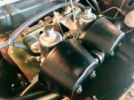
Throughout the MGB’s life, the car was fitted with two types of carburettors; they were all very similar to look at except for the American market single Stromberg version. Initially, the MGB used SU HS4 carburettors, these sat on the right-hand side of the engine as you looked at it and at a slight angle over the top of the inlet and exhaust manifold. All carburettors for the MGB were 1 1/2in diameter and fitted in the same place; the SU HS4 setup was used until 1972.
The next generation was SU HIF4 carburettors; they were introduced in 1973 for the UK market but did find their way under the bonnet in 1971 on some export models including the US cars. It wasn’t until December 1974 that the SU HIF4 was replaced with the Zenith Stromberg; this was for the North American market only. These had an automatic choke instead of the pull-and-twist choke found on all other MGB models


Early HS4 style carburettors
Exhaust System
Who can forget the sound of the MGB when it’s first fired up, and the distinctive roar emanating from the rear of the car? The exhaust system helps make the MGB recognisable from the sound of all other classic cars. People who love these cars will have a smile on their faces, which makes them glad that these cars still exist.
The exhaust system was made from mild steel and ran the full length of the car and mated up to the cast iron manifold. There were three types of manifold one for the early cars 1962 -1970 which had a thicker flange and one for 1970 onwards which used a thinner flange.
The North American cars from late 1974 had the other version that used the single carburettor system for emission control; these had a single downpipe. In 1975 a catalytic convertor was fitted just below the manifold for the strict Californian laws and these were eventually rolled out on all North American MGBs.
Inlet Manifold
The inlet manifold had many different variations depending on the exhaust manifold and carb setup, the changes are detailed below;
| INLET MANIFOLDS | ||
| FLANGE | CASTING NUMBER | |
| 12H911 | THICK | 12H708 |
| 12H1397 | THICK | 12H1398 |
| 8G767 | THICK | 12H2568 |
| 8G774 | THIN | 12H2568 |
| CHM171 | THIN | 12H2568 |
| 8G767 | THIN | CHM171 |
| 8G774 | THIN | CHM171 |
They all had the same casting numbers but did have different flange thicknesses; there were also differences on the plugs, some have them at the top as some are cast, and some are brass plugged.
The exhaust itself saw minimal changes and was the same for both Roadsters and GT’s the most noticeable change being the rear tailpipe changing when the rubber bumper cars emerged as the pipe was angled downwards away from the bumper for extra clearance. In contrast, the chrome bumper exhaust exited straight out. The rear silencer is cylindrically shaped with a flatter middle box. These materials changed very slightly to improve the life expectancy of the exhaust and on some versions to quieten them down, this was required for cars sent to Switzerland when the noise level regulation was set at 82dB in the late ’70s.
Standard MGB 1800 exhaust system
Rubber bumper tailpipe
Sports systems with straight-through pipes are available to give your MG that added power & noise but it can get a bit tiring on a long journey.


Choke Cables
The old-fashioned choke was fitted on nearly all cars during the ’60s, ’70s, and even the ’80s. It has since long been replaced with modern technology, especially on fuel-injected cars that do all the work for you. Still, back then we had the pre-starting routine, which was; ignition on, choke full out, crank it over and wait for the engine to fire into life, and gradually push the choke in as the engine warmed up. This is what makes driving a classic car, like the MGB so magical as it transports you back to a simpler time when you needed a real key to start your vehicle.
You were part of the operation learning how to start it up, taking care not to flood the carburettor, and remembering to push the choke in as it started to judder on you. This is driving, it’s an art that is disappearing as many people are alien to choke cables, seeing one with a washing peg holding it in place is somewhat unheard of nowadays.
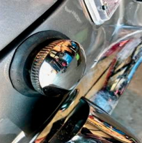
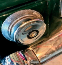
The original had a simple round knob with a ‘C’ logo on the front. This was fitted from 1962 – 1970 then it changed to a similar-looking, but slightly larger one. The new one had a ‘fan’ logo on the front and was used on the HS4 carburettors.
The later HIF Carburettors for the 73-74 chrome bumper cars used my own choice of cable and knob until 1976 when the’ T’ style knob was fitted and remained this style until the end of production. Other variations for North American cars were used; even a square-style choke was installed at some point.
Fuel Tanks
Initially, the fuel tank on the MGB was fixed to the car with two metal straps that held the fuel tank to the underside of the car. These were quite fiddly to fit and did cause corrosion issues over time to the relatively small 10-gallon tank.
The fuel gauge came from Jaeger for the cars up to GHN347462 and Smiths gauges were used after this. From 1965 the fuel tanks were altered and enlarged to 12.7 gallons and all Roadster and GT models were fitted directly to the body, the tank itself had fastening holes all around the top of the tank to bolt it up under the boot floor area.
This fuel tank remained until the end of production but with a small modification, when the drain plug was removed in January 1974. The rubber bumper car tanks from 1977 had the pick-up feed for the fuel coming from the sender unit and not a separate pick-up that can be found on the cars from 1965 to 1976.
As a result of this change, the pickup of the sender units changed, in 1962 they had a screw-in type tank sender unit, and in 1965 went to a locking ring fit which simply slotted into place with a seal and ring used and locked by a larger circular ring, the final tank unit went from 1977 onwards with larger style sender unit with a built-in fuel pick up.
Tank sender unit for cars 1977 -1980
The fuel supplied back in the heyday of the MGB was of the four-star variety, which they ran best with, but since the demise of leaded fuel in the year 2000 many cars have been converted to run on unleaded petrol. Some owners prefer to use an additive with unleaded fuel; I have found that the use of higher-octane fuel always seems to make the MGB run smoother.
Filler Necks
Yes, even these changed over the years, and not the most thought-provoking section but enough to note the changes. The fuel tank filler point came through the boot floor, which connected to the filler cap, and the tubing mated them together. The angle did change, all cars up to 1976 had the sloping filler neck and then it was altered to a straight vertical design, so the connecting tube and filler neck were adapted to allow for this alteration.
Fuel filler neck
The North American cars did see several changes, not only with the filler neck but also the fuel tanks as part of the regulations and to help prevent fuel spillages and the escape of fuel vapours. If you have seen a US-imported car and looked in the boot, you will have noticed a vapour separation tank, which was fitted on the inside close to the rear wheel arch. These cars were also equipped with a different filler neck to prevent you from using any other fuel as the neck was restricted and designed only for unleaded petrol.
Filler Caps
A round plain filler cap was used from the beginning and was of a non-locking variety; this started as stainless steel before going to chrome in the first few years. Some filler caps again aimed at the North American market will have had a non- venting type. Many aftermarket caps are available, and most will have been changed to a locking style to prevent the theft of fuel as the cost spirals. However, these were not big problems back in the ’60s, and the ’70s were just a sign of the modern era.
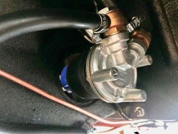
FUEL PUMPS
The MGB was fed its fuel by a SU fuel pump that sat under the rear wheel arch near the battery compartment. The gentle tick of the pump as you switched the ignition on was always comforting much more so than when it ran continuously as you found out you had run out of petrol. The first pump used ran until August 1964 when it was replaced but with only minor alterations to the body of the pump.
None locking petrol cap
Locking petrol cap
Early 1968 saw an additional breather when the pump changed, in 1974 another rubber bumper model changed, and the fuel pump mounting was moved to the boot area. It sat half in the boot to the back right area and half out of the car and was covered by a black metal cover for protection. The last fuel pump change in January 1977 was merely an updated version with updated parts for improved efficiency and supposedly quieter. Now more modern pumps are an option as things have progressed since these were designed, but the positioning remains the same.
Fuel pump in its location
Accelerator Cables
The accelerator cable was an item that can be defined by either chrome bumper or rubber bumper cars. Other changes to the cables were the length to accommodate either right-hand drive cars or left- hand drive cars; the left-hand drive car cable was shorter.
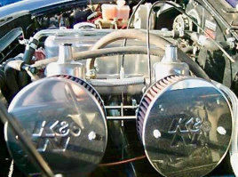
AIR FILTERS
The air filter bodies were largely black, almost cone-shaped, and dominated the right-hand side of the engine bay as they perched on the side of the carburettors. They were four-piece and consisted of a back plate which held the alloy plate which then mated to the carburettor, next was the outer casing which housed the paper element.
The same style was used throughout the production with changes occurring in 1971 when Unipart labels replaced the Cooper ones because the supplier changed. Some minimal alterations were made to the casing for the next cars when the air intake curved round unlike the earlier straight filter housing.
Air filters
Air filters of different styles
Ignition System
The ignition system was a very traditional setup for the time and was used throughout the life of the MGB. It consisted of a coil, contact breaker points and condenser distributor, plugs and plug leads. You will find many cars now will have been updated with electronic ignition systems, but none of that modern wizardry was around when the MGB was first revealed.
A 25D Lucas distributor was fitted from 1962 through to 1974, with a few minor tweaks it remained largely the same apart from the cap which went from a side entry to a top-entry cap. In 1974 the 45D distributor was used. Plug leads were changed for the different markets and some were fitted with suppressed leads for vehicles heading to France and Canada, before they were provided to all as standard. In 1975 an electronic ignition system was used on export cars to North America for the models that had a catalyst exhaust.
The later 45D distributor had a combined amplifier and vacuum unit that was attached to the side of the main body of the distributor. However, some had an amplifier remotely fitted in the engine compartment.
The timing on a static engine was 10 degrees BTDC on the high-compression version and 8 degrees on the low-compression variant; the firing order was 1- 3-4-2.
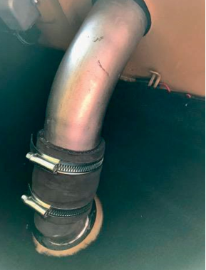
Engine Cooling
Cooling was taken care of by a large radiator that sat in front of the engine; it was cooled by a belt- driven metal fan connected to the crankshaft pulley that also powered the water pump.
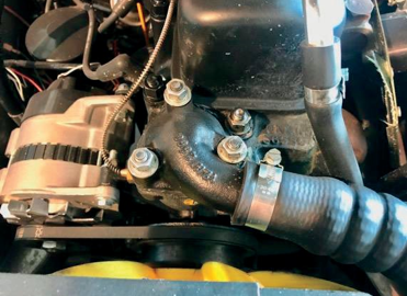
Thermostat housing
A thermostat positioned on the cylinder head regulated it all. The MGB often ran cold with the continually moving airflow that kept the temperature down as the fan ran at the speed of the engine.
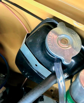
Expansion tank
It was only for the 1977 model onwards that electric cooling fans were fitted which helped the car warm up quicker and spun the fans into life when the sensor told it to start. The only exception to this was the V8; it was equipped with twin electric cooling fans mounted on brackets just in front of the radiator, they did have to work that little bit harder to keep the engine cool. The bigger manifolds on the 3500cc unit gave off more heat than the entire engine.
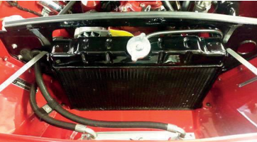
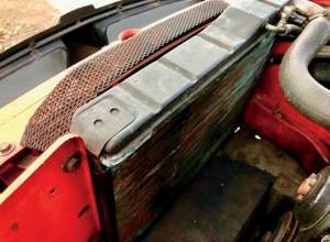
The radiator was mounted on a black cowling that bolted to the inner wings at the front of the engine bay. The first type of radiator fitted had an extended filler neck with the diaphragm having a cutaway to accommodate this. In 1967 the next type of radiator was introduced, not much different but the filler cap was now part of the radiator body that looked neater, and no need for any alterations to the radiator-mounting surround.
The third and final type of radiator used appeared first on the V8 cars and then was standardised on all models from 1976 with the mounting much further forward, as the engine layout had changed, the mountings for the radiator were part of the bulkhead layout. The electric fan was then mounted between the front bumper and the radiator with a black mesh cowl used to protect any fingers getting in the way of its operation. The majority of cars used a single electric fan although the V8 and some North American models did have twin-cooling fans.
The thermostat was designed to open at 82 degrees C that was the standard fitment; there was an option of a 74 degrees C for warmer climates and also an 88 degrees C for cars going to live in colder parts of the world.
An expansion tank was added for the later 1976 onwards cars as part of the semi-sealed system, and this was fitted on the right-hand corner of the engine bay, unlike the V8 version that was on the front left-hand side of the engine compartment.
The cooling fan itself started off as a three-blade metal item that was painted yellow in 1974 it eventually became a seven-blade plastic fan for all
UK cars. North American models used the three- blade metal fan and from 1967 went to a six-blade metal type before switching to the seven-blade plastic fan in late 1972. As mentioned earlier, the electric cooling fans took over in 1976.
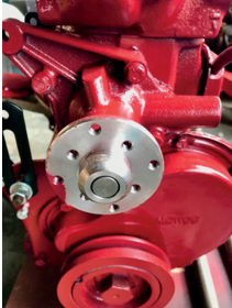
The water pump
The water pump that was located on the front of the engine had only a few variations, the early three- main bearing engine was unique to this model, and the five-bearing engine water pump had two main types that had different depths. These could be fitted to any model providing the correct pulley was fitted. One other pump used was for the US and Canada, which featured a smog pump and was altered to allow clearance for the smog pump brackets.
A radiator on an early style car
A radiator on a later Rubber bumper model
The MGB was initially offered with an oil cooler as an optional extra but became standard in 1964 with the five-main bearing engine. This is mounted on the front panel behind the chrome grille in front of the radiator, with two rubber hoses snaking through the cowling to connect to the engine.
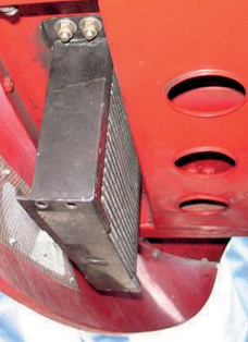
Oil cooler in front of the engine bay
The oil cooler on early cars was 10 rows, but a switch to a 13-row cooler was used until 1974 when it reverted to 10 rows and its position changed, as it was no longer fitted underneath the front panel behind the valance.