MGB – To B or not to B?
Chapter 6
![]()
Chapter 6
Suspension, Steering, Braking, And Wheels/Tyres.
Sydney Enver and chassis engineer Terry Mitchell explored several alternatives for the suspension layout in hopes of addressing some of the ride issues without sacrificing handling. The ideal solution would have been to reduce the rear un- sprung weight by using either an independent rear suspension or a De Dion axle. However, cost considerations soon put a stop to either.
The MGB had a single and very defining virtue, which was its directness and the way the handling was predictable. It wasn’t sophisticated, nor was it even very civilized, with no fancy additions or ground breaking enhancements. It simply did the job intended; the car handled reasonably well.
For its time, it was comfortable enough to live with, wherever you pointed it, it went with minimal fuss.
To compare, similar cars like the Sunbeam Alpine, which admittedly was more comfortable, were let down by a more sedate feel that lacked what a sports car was supposed to be.
The MGB handled the way most buyers expected a sports car to behave; the simple design lasted well and was pretty much the same throughout production.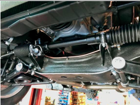
Front cross member showing steering rack and lower spring pans
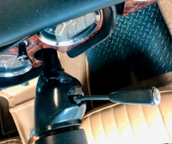
The front suspension connects to the cross member, and four long bolts fix it with lock nuts that are visible above the chassis legs. The lower wishbones attach to the cross member and between them the spring pan assemblies sit.
The front shock absorbers fixed to the top part of the cross member with four bolts, the oil filled lever arms hung forward of the kingpin assembly to attach everything, and the coil springs located between the bottom pan and the underneath of the cross member.
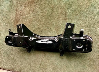
The bare cross member
The front beam could be removed as a complete unit if needed to work on the suspension, but it is much easier to attach it to the car as it keeps everything, including the steering rack stable. The front beam included a towing eye which was attached from early 1962, but it was not fitted from the start of production, it was included in November 1966.
Standard Front suspension and shock absorber.
Uprating the front suspension is a popular upgrade; this example has been fitted with a telescopic front kit to improve handling.
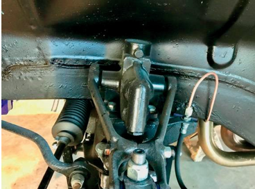
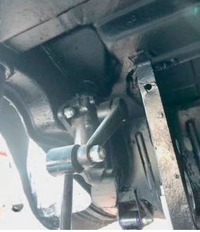
The front kingpins held everything together from the shock absorber at the top to the bottom pans, which housed the front springs. The kingpins had two grease points initially. A third was added in 1963, we all know the importance of keeping these lubricated. A small amount of regular maintenance
with grease does stop these from drying up; if left, they inevitably need replacement.
Everything was mounted using rubber bushes from top trunnion to wishbone arms; the pure simplicity of the design made them simple to work on; they were not over-engineered.
Kingpin and stub axle assembly
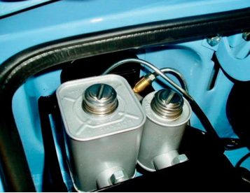
Initially, MG offered a front anti-roll bar as an extra, when the GT was introduced in 1965 it became a standard fitment. The Roadster followed suit in 1966, this did help tighten everything up at the front and made the handling more direct with a much more positive feel about it.
Front anti-roll bar
The front springs differed slightly from the GT to the Roadster and were somewhat longer with a different spring rating to help compensate for the extra weight the GT carried. In 1972 the front springs on both Roadster and GT models changed, slightly longer springs were used, and this increased the ride height by 0.5in.
The next major overhaul was the rubber bumper model, which I believe was the most controversial change; this was all due to the US market, which dictated how things had to be done. The ride height increased by 1.5 inches; this did nothing for the handling of the MG but was necessary for US regulations, the increased bumper height completed the new shape.
The front cross member changed slightly to make this happen, the new one was then used on all cars from this period through to the end of production, this included the V8 version. The cross member had two main variations, one for the chrome bumper cars, and the other for the Rubber bumper model, the only change to these were the RHD, and LHD versions that differed where the steering rack was mounted. The front springs were now the same on both Roadster and GT; however, the front anti-roll bar was updated for the GT model. It was omitted on the early rubber bumper roadsters until the 1977 model car when the uprated version was included on all MG’s as a standard fitment.
2 Side views of the MGB shows the ride height of the chrome bumper Roadster which sits a little lower compared to the Rubber bumper version.
The rear suspension set up on the MGB was again an aged but effective design; the rear axle was secured in place by the leaf springs attached from the front spring hanger mounts to the rear connection just behind the rear valance. The oil filled lever arm shock absorbers were joined by two large bolts behind the inner wheel arch; these had link arms that connected the shock absorber to the base of the leaf spring by a heavy mounting plate.
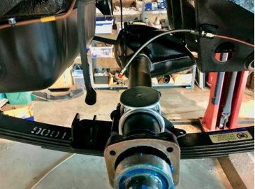
Rear axle and leaf spring
The rear suspension on the MGB was sufficient for the car but, it could be a handful, especially in the wet. However, many upgrades are available today to improve the handling, they do sometimes compromise the comfort. Yet, unless you are pushing the car a little too hard, the factory setup at the rear is very predictable and not too firm.
Rear spring
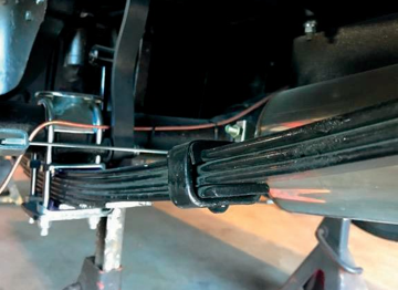
The springs were different on the Roadster compared to the GT. Initially, the Roadster used a six-leaf system with no interleaving, but from 1963 onwards, interleaving was included. Also, a fraction softer spring was used to aid in the lowering of the car at the rear.
When the GT was introduced, it had seven leaf springs as the GT carried more weight to prevent the car from sitting down too low, they did tend to soften quickly and provide a lowered ride height soon after delivery.
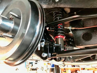
A further step-up are these telescopic rear shock absorbers with a full 5-link rear suspension upgrade bringing the MG into almost modern- day standards.
Standard Shock absorber and link
We have seen this happen previously when the MGB was sadly transformed into the rubber bumper version and the rear springs were stiffened. The spring hangers were lengthened to get the ride height increased for the American market; the shock absorber links were also extended to match.
The increased ride brought about a lot of negative comments about the car’s looks and the handling issues this change made. The MG was not as agile as before, and it was quite noticeable, in June 1976 a rear anti-roll bar was fitted which did tighten things up and made the MGB that little bit sharper, this helped stretch the car’s life out longer but maybe did not silence the critics only pacified them a little.
Axle:
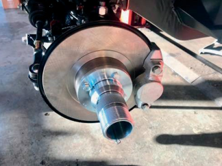
The rear axle of the MGB had two main variations, the first, known as the banjo type, was used on cars from the start of production and had a one-piece casing, the differential could be mounted directly into the housing, this style of axle was fitted until 1966.
When the GT began production, the Tube axle took over and was fitted on both models; however, it is noted that some Roadsters were still being fitted with Banjo axles, the Tube axles were standard from chassis number GHN3132923 onwards. The ratio of the Banjo axle was 3.9:1, although some competition use differentials were also offered; they were not a standard fit for a factory car.
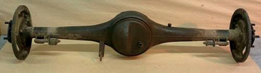
Banjo axle
The Tube axle was a much stronger unit while still retaining the same ratio of 3.9:1, for all models apart from the MGB GT, V8 as well as the automatic version, which used 3.7:1.
Both axles mounted into the car in the same fashion, they were held in place by the rear springs, these attached to it at either end using the long U bolts. The overall width of the axles did vary depending on which wheels were fitted as the hubs differed on either version with wire wheel cars nearly 2in shorter than the steel wheel version.
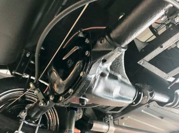
Tube axle
Both types of differentials are attached to the gearbox with a prop shaft to complete the connection.
The rear end had a universal joint that was attached to the axle; the other end had a splined section for
the gearbox. The prop shaft had a few variations depending on the axle and gearbox combination.
Prop shaft length 1962-1965 30 inches (76.2cm) banjo axle with none overdrive three synchro gearbox 31 1/8 inches (78.9cm) banjo axle with 3 synchro overdrive gearbox
1965-1968 31 1/8 inches (78.9cm) tube axle with three synchro none overdrive gearbox 32 inches (81.3cm) tube axle with 3 synchro overdrive gearbox
1967 onwards 31 1/8 inches (78.9cm) tube axle was used for all models until the end of production.
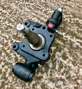
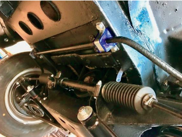
Steering System
The steering on the MGB was operated by rack and pinion. It was the same style throughout the full production run; the only changes to occur were the very early steering racks, they had a grease nipple that was removed in 1965 and the rack was altered to suit the rubber bumper cars. The length of the shaft was increased as the columns changed for the rubber bumper models, as did the angle of the rack itself.
The changes made to the cross member meant the steering rack sat slightly differently where it met the steering column; it was much closer inside the bulkhead. The rack had a slight modification in June 1976 with a lower ratio but looked the same. The steering rack joined the column with a universal joint, and only two types were fitted, one for the chrome bumper model and the other for the rubber bumper version.
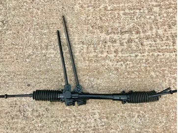
The different lengths of the steering shaft can be seen in this photo between the chrome bumper which is shorter compared to the rubber bumper steering rack.
Although the steering rack did not change much, the actual steering columns had several variations over the years. There were four steering columns fitted; the first ran from 1962 – 1967 and then 1967 – 1969, after that, the column changed again for the 1969 – 1976 version and finally the last offering from 1976 – 1980. Each of the four columns had different splines, which meant the steering wheels could not be swapped between different years.
Steering wheels
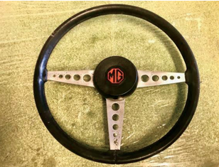
The early style steering wheel was an elegant, but large wheel with its wired three-spoke design, it did make parking and manoeuvring quite easy, although legroom was limited due to the size of this wheel. This style was used from 1962 to 1969.
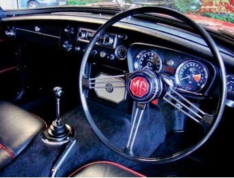
Early 3-spoke steering wheel
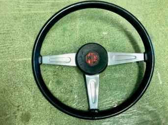
In 1969 the style of the steering wheel changed to a slightly smaller item, which was 15.5in diameter, and the outer rim covered in faux black leather and with a three-spoke design in alloy with each spoke having five holes in each and a black central finisher with an MG logo in the middle. The horn was at the end of the indicator stalk in 1971 and moved back to the centre of the steering wheel.
MK2 Steering wheel
In 1973 a new steering wheel design was fitted, it was the same size with the same faux leather rim, but no holes, now there is a stamped slot in each spoke, but this was short-lived.
During the same year, they were replaced with virtually the same style wheel, with no slots now just an impression of where they would have been stamped out. This wheel was used from 1973 through to the early rubber bumper cars and lasted until 1976. The horn remained in the centre of the steering wheel.
The steering wheel with pressed slots. This style was also used on all the MGB V8 cars produced
The last style of wheel used was the rather plastic- looking all-black 4-spoke wheel, likely this was a fashionable look at the time but the lack of any contrasting colour and against the all-black dashboard it seemed to get lost amongst a sea of plastic-looking finishes. The horn was now placed on the indicator stalk, and the central MG badge was the only thing that helped brighten things up.
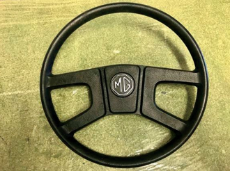
The final style of steering wheel
The steering columns were not originally fitted with
steering locks for the UK market; however, some other countries where the MG was offered for sale did have the option for steering locks.
It wasn’t until 1970 that the UK cars had the steering lock fitted as standard as it was soon to become a legal requirement shortly after in 1971. It was the North American cars that used the steering lock from 1967, which was located on the right- hand side of the column and hidden inside the cowl.
The majority of the early cars had the ignition switch on the dashboard, then home market cars had the steering lock below the column underneath the dash further down the foot well, it was close to your legs during driving. Finally, for the rubber bumper, the ignition switch and steering lock combination were inside the steering cowl at the top of the steering column nestled between the stalks.
It was a much more convenient location and safer, and like the under slung steering lock was attached by two sheer bolts that broke away during fitting to stop any potential thieves simply unbolting it.
The steering cowls that covered the column increased in size on each update to hide the wiring and workings of the horn and stalks. The first steering cowls were black plastic with a cut-out for the indicator stalk and operation, they fitted neatly over the column and butted up to the back of the steering wheel.
The cowl changed for the rubber bumper cars when the column grew in width, and the wiper switch was moved to the stalk, so one side operated the indicators and high beam and the other side the wipers and washers. It was also at this point the steering column moved. Finally, the last steering column used ran from 1976 onwards, which again housed the two stalks and ignition switch, but also the light switch was positioned in the cowl, making it quite a chunky plastic cover.

Steering cowls and indicator stalks
More steering cowls and indicator stalks
Braking system:
All models had the same brake layout with disc brakes at the front and drum brakes at the rear; this included the V8 cars.
The brakes were operated by a Lockheed master cylinder, which sat in the pedal box just above the driver’s feet.
The pedal was attached to a rod in the pedal box, which pushed the master cylinder, which in turn stopped the car.
From the master cylinder, the brake pipes ran down the inner wings to the front brake calipers and the rear axle where they split off to each of the rear brakes.
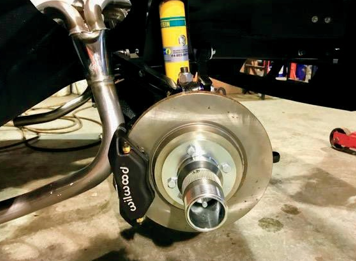
MGB front disc, calliper, and wire wheel hub.
The front brakes did the majority of the work via the brake callipers, which wrapped around the disc, they were sufficient to stop the car, and assisted by the rear drum brakes offered enough braking assistance for most.
However, anyone used to driving a modern car with the ABS systems and instant response the pedal gives can find the brakes on an MGB a little daunting at first as you do have to push the pedal harder than on most modern machines. Light effort braking is what’s commonly used today but that’s not how they were all those years ago. This takes us back to having to drive cars again, without the need for all the driver’s assistance that is available now, proper motoring like it was back in the day.
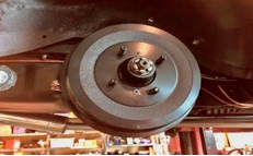
Rear brake drum.
The front brakes did not have any significant changes. The calliper discs and pads remained the same, this was also the case for the rear braking system, apart from the difference in wheel cylinders, these changed for the Roadster and GT.
Early-style brake and clutch cylinders within the pedal box
The brake master cylinders did change; they were initially a metal, box-style reservoir, with later examples using a clear plastic version. This same style of brake master cylinder was used from 1962 through to 1977 when it was changed in favour of a dual-line system.
The pedal box was altered to accommodate the new master cylinder along with the inline servo unit; this was now part of the pedal box assembly.
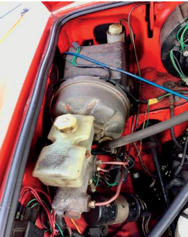
Later style dual circuit pedal box & inline servo
The braking system was improved by adding this servo unit, which greatly assisted the braking system. It was first offered as an optional extra on the UK market cars from February 1970 and then became standard in August 1973; this same remote- style servo was used until 1977.
Remote servo unit
The North American cars had a dual circuit system from as early as 1967, in some European countries, the dual circuit system was introduced in 1970. The North American cars had the later style master and combined servo from the late 74 with an improved version in 1976.
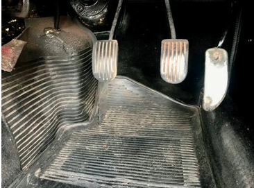
Pedals in the foot well
A few minor tweaks were made to the handbrake. But the operation of it remained pretty much unchanged, the handbrake cable was modified, and it ran from 1962-1966 for the banjo axle, from 1966-67 for the three synchro tube axle with the next running from 1967-1974 with the four synchro tube axle.
Then it ran from 1974-76 for the rubber bumper cars with a cable until finally being adapted to the use of a rod fitted across the axle from 1976 onwards.
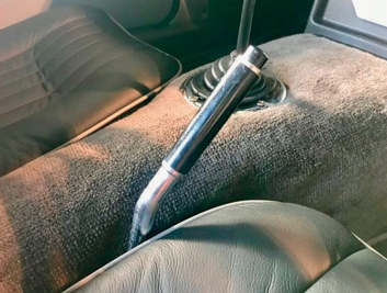
Handbrake lever
The actual lever itself changed in 1972 when the angle was changed to allow more room for the centre console and armrest that was fitted for this year. The earlier item would cause the lever to touch and your hand would get caught when applying the handbrake.
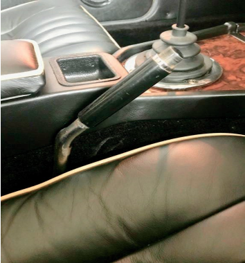
The hand brake squeezed between the centre console and seat.
Wheel Options and Tyres
When we remember the image of an MGB, many times it’s of shiny chrome bumpers and wire wheels, but the wire wheel option was not a standard fit on the MGB as they were initially supplied with the silver steel disc wheels. All wheels fitted to the MGB are 14″ in size with a four-stud pattern, the disc wheels on the Roadster were 4Jx14, and the GT version was 5Jx14 and was fitted with a plain bright silver hub cap that clipped over the central part of the wheel and hid the wheel nuts. A version with an MG logo on the hubcap was offered as a factory option from 1963-65, and then they became a dealer option until 1967.

Original steel wheels
The wire wheel option was available but had to be specified from the factory, as the installation of these requires a splined hub for the centre-locking wheel to slide over before being held in place by one large locking nut either in octagonal shape or with a two-eared design. The octagonal nut was used on most export cars from 1967 as the eared spinners were made illegal in some countries and deemed dangerous, but the UK market saw them used for a little longer.
The spinners on early cars from 1962-65 used a finer thread for the spinner, these were 12 TPI (threads per inch), and from 1965 onwards they used an 8 TPI type for both eared and octagonal spinners.

2-eared spinners

Octagonal nut spinner

A splined rear hub
The spinners were specific for each side, each one imprinted left-hand side or right-hand side, the thread was designed to match each one. They were heavy lumps, made from aluminium bronze and chrome plated. The wire wheels were an option on all UK cars throughout the production and were also fitted to several LE cars during 1980.
For the 1970 model, the next update arrived for the wheels; the disc wheels were dropped in favour of the rostyle wheel, this silver and black steel wheel was a 5JX14 in size. It was a pretty simple design with silver outer and inner sections painted black with a wheel centre that had the MG logo on which hid the grease cap for the wheel bearings. This style of the wheel came out for the GHN5 and GHD5 cars and stayed in production until the end. A chrome rostyle wheel was also available from early 1970 and the chromed section would typically be painted silver. These were offered from 1972 in the UK but were deleted from the option list on all cars from 1976.

Rostyle wheel
The last version of wheels was fitted to the LE, they were a five spoke alloy wheel in a dark grey and silver finish, these were offered for all cars from 1979 – 1980 but were standard on the LE version. The only other offers came in the form of the V8 wheel, which again was 14″. It was an intricate design in black and silver; these were also used on the Jubilee version in 1975 but painted in black and gold.
From the early style disc wheels, which do look very elegant through to the rostyle wheels and the variations for the limited edition models, each step through time shows the changes in design and the constant need to update the car’s appearance. Although many would argue that the wire wheels are a must, anyone who has spent a Sunday morning cleaning a set of wire wheels will tell you they look great, but the upkeep is constant.
Alloy Wheel Options
Many different tyre options were fitted to the MGB, and as expected of the era, they started off using cross-ply tyres with an inner tube, the chosen manufacturer was Dunlop, and these could be fitted with a white wall band for the real classic look. Radial tyres gradually found their way in, and from 1965 these were offered with the Roadster using sizes 155/14 and the GT 165/14. Inner tubes were used on all styles of wheels apart from the MGB GT V8, this was first to be fitted with tubeless tyres and slightly wider at 175/14 for extra grip.
Tubeless tyres saw their way in as standard at the entry of the rubber bumper cars and still sporting Dunlop rubber. From 1978 other manufacturers became approved, so the likes of Michelin, Firestone, Goodyear, Pirelli, and Uniroyal were used. The last of the cars with the alloy wheels fitted had 185/70/14 tyres which were a little wider again and with a lower profile.
Today a 14″ wheel is deemed small, and many MGBs have been fitted with larger 15″ wheels as the choice of tyres is far higher for this size. They also fill the arches nicely, there is a wider choice of wheels from wire wheels to Minilite style along with a few more modern alloy options and even 15″ replicas of the V8 wheel available.
